

January 18, 2005 ( last updated : February 17, 2021 )
electronics
tesla coils
high voltage
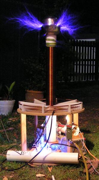
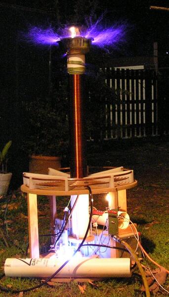
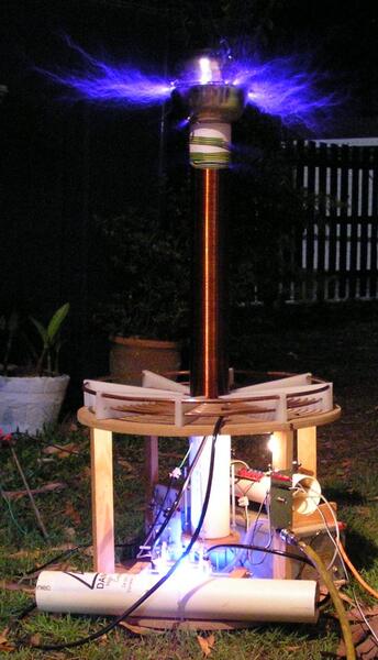
My original TC – the one that got me started on this crazy hobby. It underwent first light in July 2004 in Queensland, Australia.
It is powered by a 12kV 30mA Neon Sign Transformer, and to date has produced about 40cm Streamers (~16″).
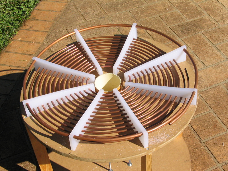
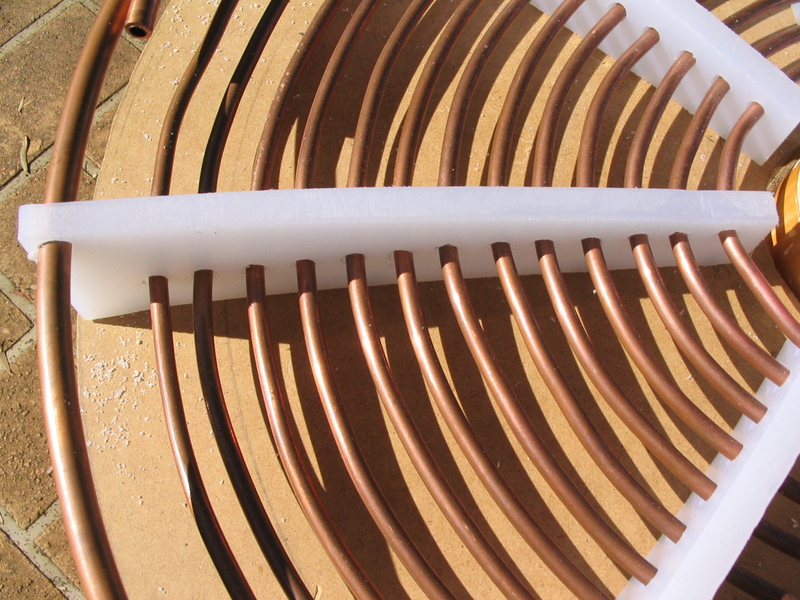
The primary coil consists of 13 turns of 1/4″ copper pipe, seperated by 1/4″. This is supported by High Density Polyethylene (HDPE) supports for insulation. These also support the strike rail, a (nearly) single turn of 3/8″ copper pipe 1″ above the primary.
The coil is mounted on an MDF base.
The secondary coil consists of about 1200 turns of ~0.5mm enammelled copper wire. It is very aged, but was acquired cheap. The aspect ratio is high at 6.17:1 due to the fact that the winding is 55cm long. This was wound using a winding jig on a lathe, and took just over 2 hours of winding time. The winding is covered in three thick coats of varnish, and there is a single coat on the form prior to winding.
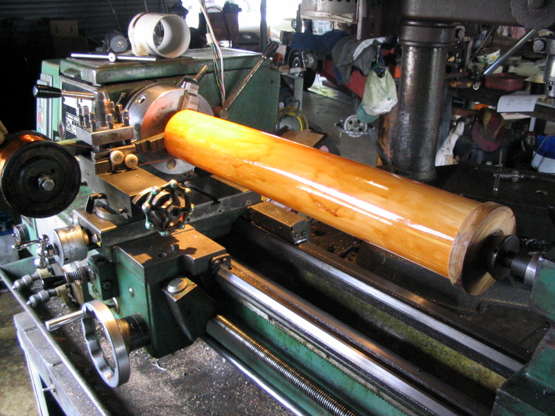
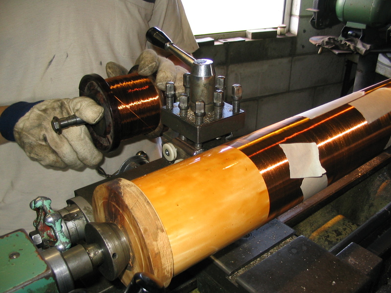
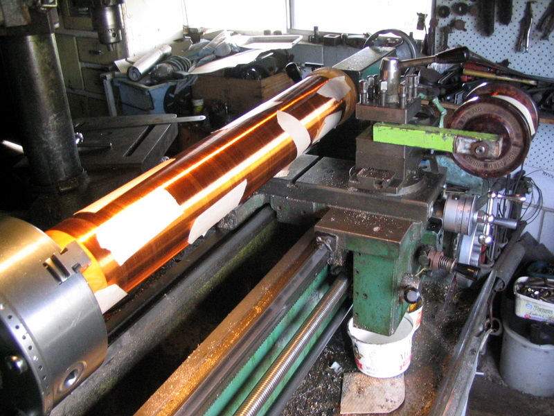
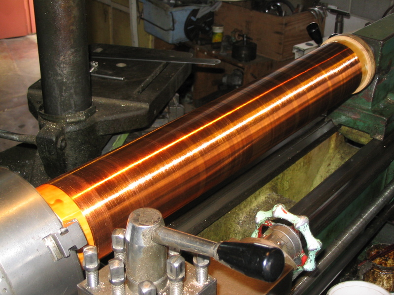
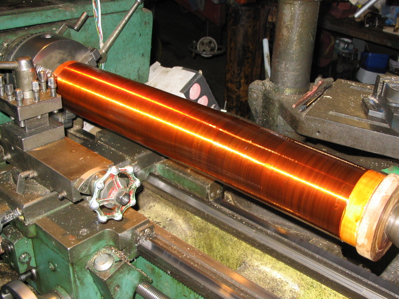
A short clip of the winding process: *[HTML]:
The primary capacitor is a bank of Cornell Dubilier 942C20P15K capacitors. Each is rated at 2000VDC, 0.15uF. 12 Capacitors are used, giving an overall capacitance of 0.0125uF @ 24000VDC. This stores 3.6 joules of energy when fully charged.
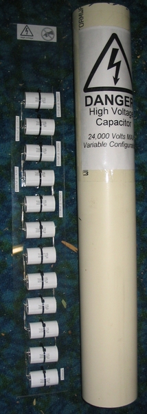
The filter is based upon the design by Terry Fritz. Living in Australia, I had a few problem sourcing the parts request in his schematic. Eventually I used RS Components for the MOV’s and High Power Resistors. The 2 60mm fans cool the 100W power resistors, as I didn’t mount these on extra heatsinks. For 30ma, they don’t even consider getting warm, and probably don’t require the fan’s in hindsight.

Currently 2x 20cm Diameter Stainless Steel Bowls from the local supermarket. Provides 8pF of capacitance.
I have manufactured 2x Safety Gaps, one pair for the the transformer (Centre Ground), and the other for the capacitor. Currently, the capacitor ones are not used, as I am using a static gap.
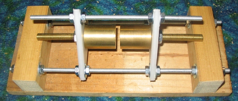
The main gap is an air blast gap, quenched with air from an air compressor. This appears to work well, but I have not tried it with any other gaps to compare. The photo below does not show the air line connector mounted directly underneath the electrodes.
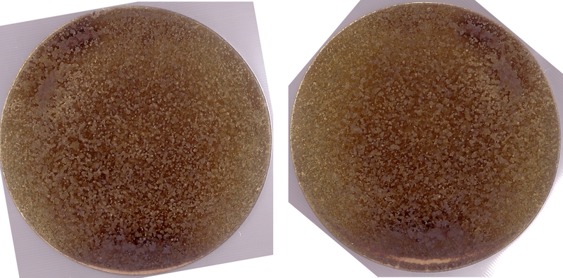
The below image is the electrodes after ~30minutes running time. I resand them every 1/2 hour of running time. The electrodes are the correct way up – ie. The bottom of the image is the bottom of the electrodes. The linked image is ~3MB BMP direct from the scanner.
18/1/2005
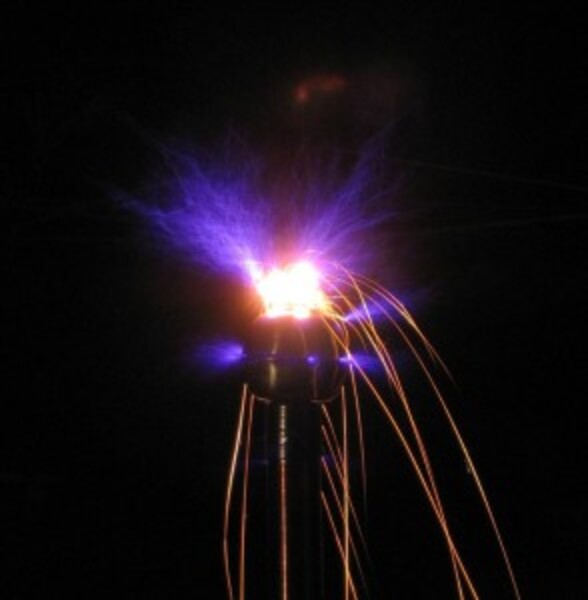
Steel Wool on top of the breakout.
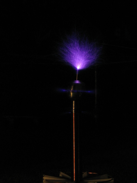
Vertical Breakout
23/12/2004
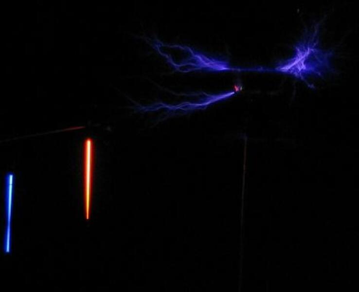
The side streamer is coming from a bolt used to connect the secondary to the topload.
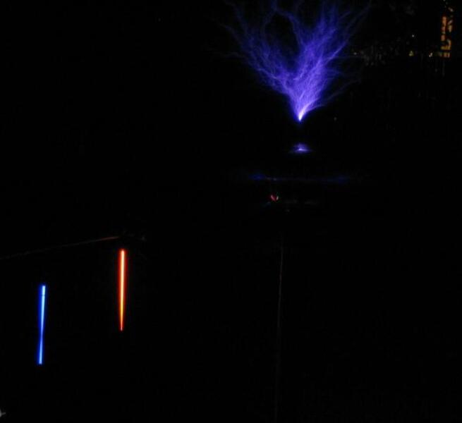
Vertical Breakout Point
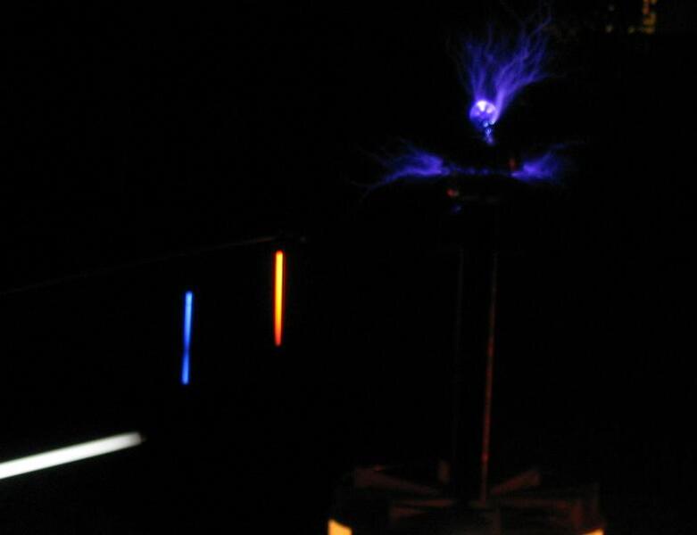
An incandescent light bulb on top of the coil.
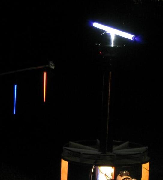
The red and blue neons are 300mm long.
8/12/2004
Originally published January 18, 2005 (Updated February 17, 2021)
Related posts :