February 07, 2013 ( last updated : February 17, 2021 )
rf
laser cutting
Ok, it is time for another blog post. I have taken a vow to share more of my projects with the world, partly in case someone is interested, partly to motivate myself to do more cool stuff! I figure neither of these are bad.
I’ve had a bit of an itch to try out radio astronomy for a few years, ever since I discovered that it was possible without spending thousands of dollars. Whilst the best performing antenna for this work is a parabolic dish (the bigger the better!), I wanted to start with a smaller, simpler, easier, antenna. I chose the helical antenna. My logic was that I should be able to see the hydrogen line on at least our closest star, hopefully enough to spurn further interest. It would also act as an ideal test platform for other related electronics such as low noise amplifiers and filters. Suffice to say, the decision was made.
After reviewing a number of the online calculators for helical antennas, I decided upon about 10 turns. This is very approximately 600mm long at 1.42GHz. The single hardest part seemed to be the coil form, so a plan was hatched to use my laser cutter and some perspex to make this easy. It turned into a fun project to parametrically generate helical antennas in Autodesk Inventor. Suffice to say, tell it the frequency, the desired plastic diameter, wire size, perspex thickness and the number of turns and it produces a set of files that can be lasercut to produce the requested antenna.
Anyway, enough talking – to the photos! If more information is required, please contact me and I will create another post!
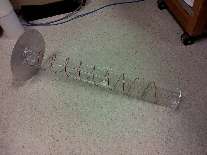
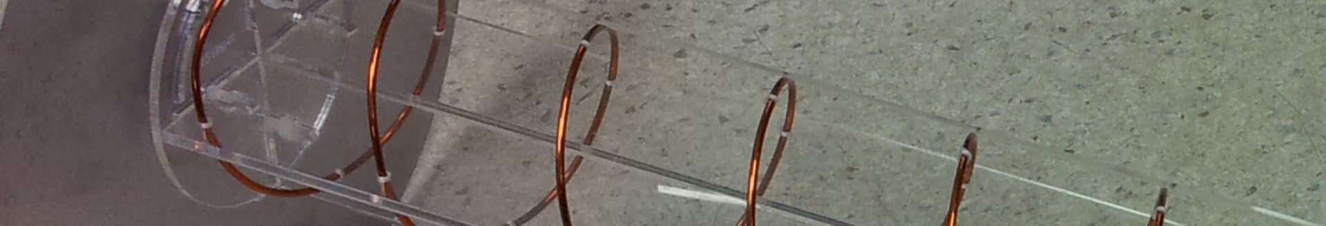
The almost completed helical antenna.
Helical antennas have a characteristic impedance around 140 ohms. To match to 50 ohm cable and connectors, some form of matching is required. When I designed the antenna, I intentionally brought the first turn in close to increase the capacitance to the ground plane, on the hope this would help lower the impedance. There are a number of other techniques that can be used, but I wanted to start with this one!
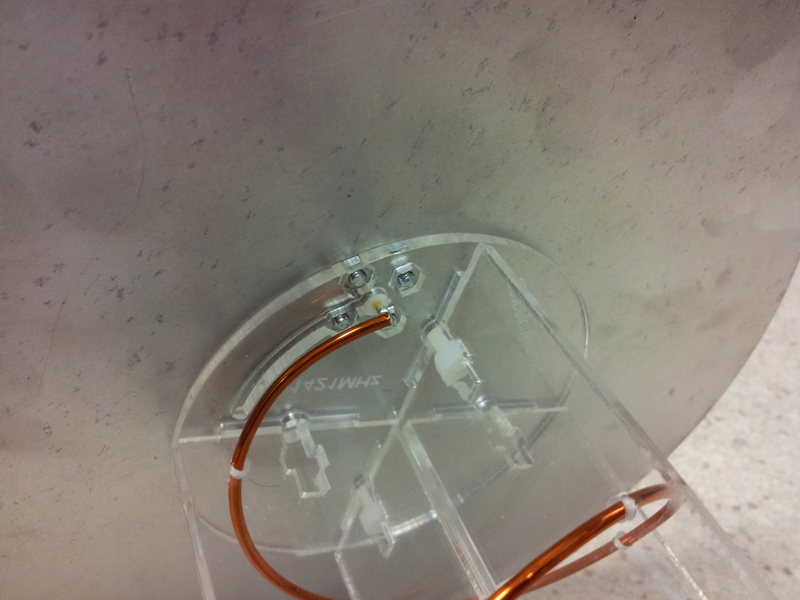
The feed connection to the SMA connector.
Luckily I have access to a VNA (Vector Network Analyser) at work that makes impedance measurements a breeze, unfortunately the easiest way to get an image is to use a camera phone. As can be seen, without any extra matching work the impedance at my desired frequency is about 62 ohms, corresponding to a VSWR of less than 1.2. To say that I am pretty happy with this is an understatement! Given that it took absolutely no effort to get it to this point! I may try to improve the match in future, but for now it is fine with me!
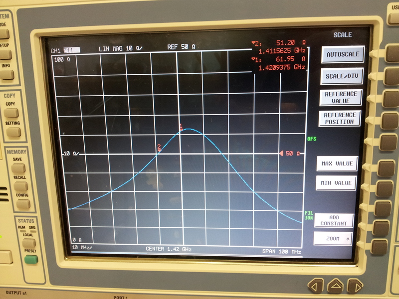
A plot of the antenna impedance.
Finally, here is an image showing how it all fits together. The slots are used with nylon screws to hold it all together.
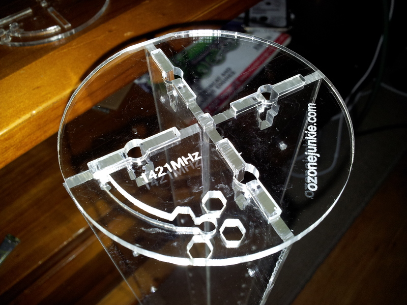
The base of the antenna, showing room for the matching wire, cutouts for SMA connector and the fixing method between parts.
Originally published February 07, 2013 (Updated February 17, 2021)
Related posts :